System Integration Context Diagrams
A System Integration Context diagram answers the question every new architect on a project asks first: what are the systems in this solution, which ones are ours, and how does data move between them and the outside world?
It is a C4-style context view, drawn fresh from the model every time you open it. There is nothing to choose and nothing to focus on first — it always shows every system in the project at once.
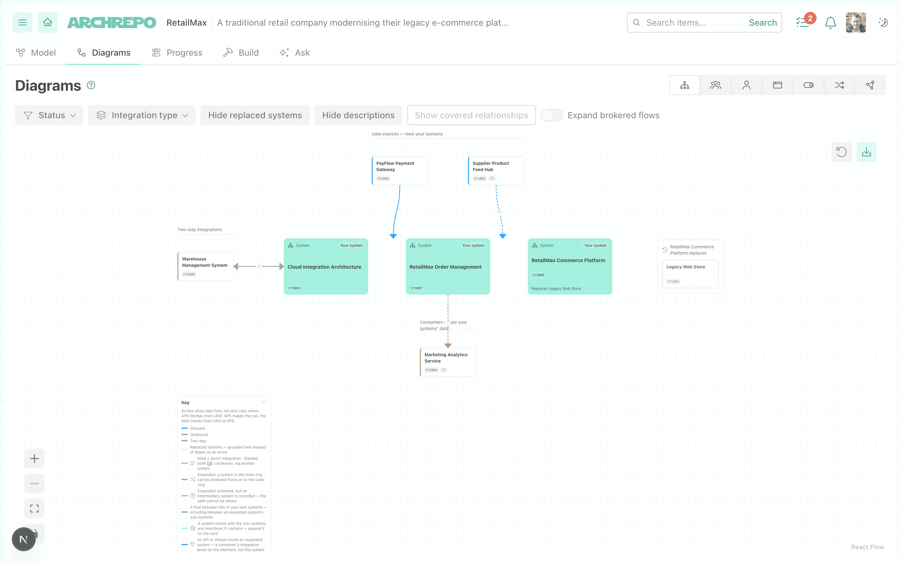
What the Diagram Shows
The project’s own systems sit together in the middle as the core band. Everything around them is an external system, grouped into a lane by how it integrates with your systems.
Internal vs External
A system counts as internal when its “External to solution?” property is No or unset — the default for a new system. Set that property to Yes and the system moves out to the edge as an external partner instead.
If nothing appears in the middle of the diagram, this is the first thing to check — see Why Is My Diagram Empty? below.
The Four Groupings Around the Edge
Every external system is placed by looking at the data-flow relationships between it and your internal systems:
| On screen | Meaning | What places a system here |
|---|---|---|
| Inbound | Data flows into your systems from this partner. | Your system fetches data from or receives data from the external system. |
| Outbound | Data flows out from your systems to this partner. | Your system’s data consumers or data recipients include the external system. |
| Two-way | Data flows in both directions. | The external system has at least one inbound edge and at least one outbound edge to your systems. |
| Replaced systems | Not a flow at all — this system has been superseded. | A replaces relationship exists between one of your systems and the external one, in either direction. |
Two-way is also where an unrecognised relationship lands. Most relationships between your systems and an external partner are one of the ones named above. A partner connected only by some other relationship type — one that carries no clear direction of data flow — is grouped under Two-way as well, since there is nothing to say it belongs in Inbound or Outbound instead.
A system with no data-flow relationship to anything internal is not shown at all — the diagram only draws partners it can actually place.
Replaced systems are grouped, not drawn as arrows. Rather than cluttering the diagram with legacy connections, every external system your project has replaced (or that has replaced one of yours) is collected into its own titled region, named after the internal system involved. Turn them off with the Hide replaced systems toolbar control once you have seen them.
Direct vs Brokered Integration
Two systems can be connected the same way on the surface — data moving from one to the other — while getting there very differently: a direct call, or a hop through some intermediary the model doesn’t necessarily show. ArchRepo tells them apart:
- Fetches data from is a direct integration — your system calls the external system itself.
- Receives data from is a brokered integration — the data arrives by some other route, such as a message broker or an integration platform.
A card in the Inbound or Two-way grouping carries a “via another system” badge when every one of its edges is brokered. The moment a system has even one direct edge, the badge disappears — it counts as directly integrated, even if its other connections are brokered. The diagram is describing the system, not each connection separately.
Systems That Contain Other Systems
A system that itself contains other systems shows a “Contains N” button on its card, where N is how many sub-systems it currently holds. Click it to expand the card in place:
- Each sub-system is drawn inside its parent, and its own integrations move onto the sub-system that actually owns them, rather than being attributed to the parent.
- While the card is collapsed, those same integrations are still shown — but as the parent’s. Where several of a collapsed system’s sub-systems all integrate with the same external partner, those are drawn as a single arrow labelled with how many flows it represents (for example, “3 flows”), rather than one line per sub-system.
- Expanding a card can therefore change how many arrows you see to a given partner — that is the collapsed view consolidating, not a sign that something has gone missing from the model.
Which cards are expanded is held in the page address, so ?subsystems= in a shared link reproduces the same systems expanded for anyone who opens it.
The Toolbar
This diagram is read-only. Every control below changes what is shown, never what is modelled — to change the picture, change the systems and relationships behind it.
| Control | What it does |
|---|---|
| Status | Show only systems at the statuses you choose (Draft, Approved, and so on). Leave nothing checked to show every status. |
| Integration type | Narrow the diagram to one or more specific relationship types, drawn from whatever types actually exist between systems in this project. |
| Show/Hide replaced systems | Toggle the grouped Replaced systems region on or off. |
| Show/Hide descriptions | Toggle the short caption drawn on each connection, for a cleaner diagram when you just want the shapes. |
| Show/Hide covered relationships | A system-to-system relationship that a data flow already states is hidden by default, so the same integration is never drawn twice. Turn this on to reveal those older, now-redundant relationships as well — useful while tidying up a model that is migrating towards flow-based modelling. The button names how many are currently hidden, and is disabled when there is nothing to reveal. |
| Expand brokered flows | A brokered (“via another system”) connection can sometimes be expanded to show the actual intermediary system carrying it, when the model records one. Turning this on adds that intermediary as its own card between your system and the partner it ultimately reaches. The button names how many brokered flows can currently be expanded this way, and is disabled when none can. |

The canvas also carries a collapsible key, in the corner of the diagram itself, explaining every colour, line style and icon in use — including which stroke means direct versus brokered, and what the different card colours mean once systems and interfaces are expanded. It collapses to a single title bar once you know your way around, and stays out of the way when you print or export the diagram.
Where to Find It
Open the project’s Diagrams tab, then choose System Integration Context in the switcher. It is the first diagram in the list — the one a new user of a project is most likely to open first.
Why Is My Diagram Empty?
This diagram is built entirely from system items and the data-flow relationships between them. If it looks empty, or shows only a single box with nothing around it, the cause is almost always one of these:
- No internal systems are modelled yet. With no system in the project — or every system’s “External to solution?” property set to Yes — there is nothing to put in the core band, and the diagram shows a message rather than a blank canvas.
- Systems exist, but nothing connects them. A system with no fetches data from, receives data from, data consumer, data recipient or replaces relationship to anything internal has no lane to sit in and is left off the diagram entirely. Modelling two systems without a data-flow relationship between them is not enough — the connection itself has to be recorded.
- The filters are hiding everything. An active Status or Integration type filter can legitimately reduce the diagram to nothing. The diagram tells you this directly, with a count of what is hidden and a button to clear the filters, rather than leaving you looking at an unexplained blank canvas.
When the Diagram Is Empty
| What you see | What it means |
|---|---|
| ”No internal systems found for this project…” | No system is modelled with “External to solution?” set to No or unset. Model at least one internal system. |
| ”No relationships match the current filters…” | Your Status or Integration type filters have excluded every connection. Use Clear filters. |